Showing posts with label embedded system. Show all posts

RAILWAY ACCIDENT CONTROL

hi,
i am happy to say that i and my friend saravana pandian won the first prize in the Mepco Schlenk Engineering College, Sivakasi...i would like to share that papers abstract with you all...

EMBEDDED BASED RAILWAY SAFETY SYSTEM
-life is priceless, life protection is cheap.
Right from the splendid starting of 2010 to July 19, 2010, Hundreds of precious lives have been taken from our mother INDIA, in thirteen train accidents. The Gyaneshwari Express train derailment and Sainthia train collision are the two major accidents this year, which killed 223 passengers….
Trying to be responsible citizens of this nation, here we propose a design to reduce these accidents.
“Few can foresee whither their road will lead them, till they come to its end.”
-J.R.R. Tolkien (English Writer)
The main drawback with locomotive system in use is, even if the pilot identifies any problem in the rails, he needs at least 500 meters to stop the train using emergency braking systems, which is practically impossible. So, we send our ROVER 500 meters ahead of the train to check for any obstacles or damages found in the track (rail) using sensors and intimate to the train as well as to the nearest station via Radio Frequency with the help of a microcontroller.

LCD INTERFACING


hi friends,
In Recent years,the LCD is finding widespread use replacing LEDs. everyone would like to have it in their project to attract the visitors. similarly we too had it in our project "Power On Coin", But we made a very small, tiny mistake while interfacing and we spend nearly a week to identify that problem. But, we learned many things about LCDs in that week, that's here
INTERFACING OF LCD
 All LCD will have minimum of 14 pins, some may have few more for back LED lights. knowledge of these 14 pins is enough to interface LCD. let we have a look at those 14 pins.
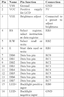


VSS:ground pin     VDD:+5v supply pin

VEE:contrast pin, by adjusting the supply to this pin we can get clarity in the display.
 NOTE: never give full 5V supply, vary it with a variable resistor(pot:10k)
RS: this register will say the LCD whether the information is command or data.
we would like to control the cursor in the display like clearing, moving the cursor in the display, entry mode, etc. this could be done through passing command by Rs=0->we can inform the LCD the information is command. respectively command words and codes are shown.
while we are passing data we should have Rs=1.
R/W:we are suppose to inform the LCD, whether the information is to be read or written on the LCD. this pin will do that work.
R/W=1->read mode
R/w=0->write mode
ENABLE PIN:very important pin of all, only when pass high to low signal to this pin, the command/data will be latched into LCD. But should have at least 450ns gap between setting and clearing this pin. because the micro controller may be working at MHz but our LCD will be working at KHz . so, we need to apply some delay else the date will not be proper.
E line is negative edge triggered- to write
E line is positive edge triggered- to read

D7-D0:information should be sent/received only through pin only this is data pin. ASCII key values of the corresponding character or command should be alone sent/received through this pin.
these are those 14 pins.
WORKING:
  • First we should configure the LCD,so we need to pass the command code. Don't send all, send only which are required.
Load D7-D0 with command code
Rs=0; to inform it is command
R/W=0; we are going to write it
E=1; to set E high
delay: to match the speed [450 ns]
E=0; low to latch the data
  • Then we can pass the information 
Load D7-D0 with data
Rs=0; to inform it is word
R/W=0/1; depends on us, whether we would like to read or write
E=1; to set E high-write/low-read
delay: to match the speed [450 ns]
E=0; low to latch the data/high to read

BUSY FLAG:
we are using delay, because the LCD need time to do some internal operation. but we cannot import exact delay, so it may slow down the process. so by using Busy flag we can over come this problem.
here, we use Rs=0 to check the busy flag bit to see if the LCD is ready to receive information. Thus busy flag is D7 and can be read when R/W=1 and Rs=0, as follows: if R/W=1, Rs=0. when D7 =1, the LCD is busy taking case of internal operations and will not accept any new information. when D7=0, the LCD is ready to receive new information.
It is better to use busy flag, rather than imparting delay everywhere use of Busy flag will make the program to run faster.
NOTE: one important thing here is, we need to send low to high signal to enable pin. since we are reading.
PROGRAM:
  • sending commands and data to LCDs with a time delay
;calls a time delay before sending next data/command
;p1.0-p1.7 are connected to LCD data pin D0-D7
;p2.0 is connected to Rs pin of LCd
;p2.1 is connected to R/W pin of LCD
;p2.2 is connected to E pin of LCD
    org 0000H
    mov a,#38H    ;init. LCD 2 lines, 5X7 matrix
    acall comwrt    ;call command subroutine
    acall delay    ;give LCD some time
    mov a,#0EH    ;display on,cursor on
    acall comnwrt    ;call command subroutine
    acall delay    ;give LCD some time
    mov a,#01    ;clear LCD
    acall comnwrt    ;call command subroutine
    acall delay     ;give LCD some time
    mov a,#06H    ;shift cursor right
    acall cmnwrt    ;call command subroutine
    acall delay    ;give LCD some time
    mov a,#'h'    ;display letter h
    acall datawrt    ;call display subroutine
    acall delay     ;give LCD sometime
    mov a,#'i'    ;display letter i
    acall datawrt     ;call display subroutine
again:    sjmp again    ;stay here

comnwrt:        ;send command to LCD
           mov p1,a    ;copy reg a to port1
           clr p2.0    ;Rs=0 for command
           clr p2.1    ;R/W=0 for write
          setb p2.2    ;E=1 for high pulse
          acall delay    ;give LCD some time
         clr p2.2    ;give LCD some time
         RET        ;return
   
datawrt:        ;write data to LCD
           mov p1,a    ;copy reg a to port1
           setb p2.0    ;Rs=1 for data
           clr p2.1    ;R/W=0 for write
           setb p2.2    ;E=1 for high pulse
           acall delay    ;give LCD some time
           clr p2.2    ;E=0 for high to low pulse
            ret        ;return

delay:    mov r3,#50    ;50 or higher for fast CPUs
here2:   mov r4,#255    ;r4=255
here:     Djnz r4,here    ;stay until r4 becomes 0
            Djnz r3,here2    ;stay until r3 becomes 0
            return        ;return
             end

  • sending commands and data to LCDs using busy flag  
 ;check busy flag before sending data,command to LCD
;p1=data pin, p2.0=Rs,p2.1=R/W,p2.2=E pins
    mov a,#38H    ;init LCD 2 lines,5x7 matrix
    acall command     ;issue command
    mov a,#0EH    ;LCd on, cursor on
    acall command    ;issue command
    mov a,#01H    ;clear LCD command
    acall command    ;issue command
    mov a,#06H    ;shift cursor right
    acall command    ;issue command
    mov a,#86H    ;cursor: line 1,pos 6
    acall command    ;issue command
    mov a,#'h'    ;display letter h
    acall data_dispaly     ;issue data
    mov a,#'i'    ;diaplay letter i
    acall data_display    ;issue data
here:    sjmp here    ;stay here

command:
    acall ready     ;is LCD ready?
    mov p1,a    ;issue command code
    clr p2.0    ;Rs=0 for command
    clr p2.1    ;R/W=0 for write
    setb p2.2    ;E=1 for high pulse
    clr p2.2    ;give LCD some time
    RET        ;return

data_display:
    acall ready    ;is LCD ready?
    mov p1,a    ;copy reg a to port1
    setb p2.0    ;Rs=1 for data
    clr p2.1    ;R/W=0 for write
    setb p2.2    ;E=1 for high pulse
    clr p2.2    ;E=0 for high to low pulse
    ret        ;return  

ready:
    setb p1.7    ;make p1.7 input port
    clr p2.0    ;Rs=0 access command reg
    setb p2.1    ;R/w=1 read command reg
;read command reg and check busy flag
back:    clr p2.2    ;E=0 for low to high pulse
    setb p2.2    ;E=1 low to high pulse
    jb p1.7,back    ;stay until busy flag=0
    ret        ;return
  
    end

i said that we made a very small mistake and we were spending a week in it. the mistake is that,we gave +5V
to VEE pin, we need to vary it as we vary contrast in TV. But, we thought we made mistake in the program and we were checking the program for 5 days
so, always view the problem in various angle, that will give solution quickly...

ACCIDENT CONTROL FOR AUTOMOBILE

Friends,
here is my second paper with my friennd Rajesh khanna... EMBEDDED BASED AUTO MOBILE COLLISION PREVENTION... this paper is entirely different from my last paper... expect the title everything is on our own... it is completely our paper... we took nearly a weak to complete this paper... while working on this paper we learnt many recent concepts like range finder, how to select controller, braking systems, ABS, etc... it was very enjoyable and interesting to us...
And this paper got selected in ANNA UNIVERSITY, COIMBATORE and KARUNYA UNIVERSITY..
More important is that we won second prize for this in ANNA UNIVERSITY,coimbatore...
here is that interesting paper for you


EMBEDDED BASED AUTO MOBILE COLLISION PREVENTION 

Most of the automobile accidents could be avoided if the brake had been applied at proper time and at proper distance. In this paper we are using embedded system which could be embedded in the automobile to remove the driver’s reaction time from the situation. The system, consisting of controllers, which analyzes possible accident situations based on the vehicle separation distance, their relative velocity and a static friction coefficient that represents the road conditions. The controller determines the sufficient brake pressure required to prevent collisions while providing a smooth ride for the vehicle’s passengers. 

Our work is to design controller to automate and optimize the application of brake pressure to an automobile’s brakes at proper time. So first requirement implies that the two vehicles should never have any physical contact, while the second one implies that the brakes should be used only in the amount necessary, e.g., they should not undergo large excursions to make small adjustments.

In general, if the automobile in front decelerate, then the vehicle behind it must decelerate to avoid the collision.  Here, the controller tracks the vehicle and have its velocity as reference and applies the appropriate brake pressure at the proper time. So, the controller automatically decelerates to match the velocity of the tracked vehicle and avoid a collision. 

IMPORTANT PARAMETER
The parameters that we took to avoid collision are
  •  separation between the two vehicles
  • velocity with which they approach each other
  • surface conditions
  For calculating these three parameter, Laser range finders could provide the first two measurements, while wheel-slip sensors currently used for automobile Traction Control Systems or Anti-lock Breaking systems (ABS) could estimate could estimate the third measurement.  

MODULES
we have three modules, they are
  •       distance finder
  •       intelligent control module
  •       braking system 
working
here,the distance finder finds the distance between the vehicles and reports to the controller.The controller processes data and  calculates the percentage of braking. this braking is coupled with actual braking of the ABS unit..


FIRE ALARM

Hi friends,
This is our first mini project,worked out by myself and my friends saravana pandian , Rajesh.,FIRE ALARM.It is a very simple circuit. This project taught us the most important thing in life that there is a huge gap between the theory we learn and what happens in practical life.we faced so many difficulties to make this circuit work which helped us to learn more,and this gave us the interest to go more practically.But we didn't present it because we had one more weak to go. so, we tried seismic sensor and we presented it.
Here is our first work....

FIRE ALARAM


Fire accidents can be prevented if timely alarms are available. The circuit presented here warns the user against such fire accidents. The circuit should be placed in fire-prone areas such as a kitchen. Everyone is aware that when anything catches fire, smoke is produced. When this smoke passes between a bulb and an LDR, the amount of light falling on the LDR decreases. This causes the resistance of LDR to increase and the voltage at pin 2 of IC 555 goes below 1/3 Vcc, thus triggering IC 555 which is used here in bistable mode. As a result the voltage of pin 3 goes high. This high voltage (approximately +9V) completes the supply to the COB (chip-on-board). The signal generated by COB is amplified by an audio amplifier. In this circuit, the audio power amplifier is wired around IC TDA 2002. The sensitivity of the circuit depends on the distance between bulb and LDR as well as setting of preset VR1. Thus by placing the bulb and the LDR at appropriate distances, one may vary preset VR1 to get optimum sensitivity. Reset switch S1 is provided in the circuit to switch off the alarm after the fire has been noticed by the user.

BLUE EYES TECHNOLOGY

This is my first paper.. with my friend saravana pandian.. We just want to learn and do something.. Fortunately we got this topic and we took seminar on this topic in VELAMMAL COLLEGE OF ENGINEERING AND TECHNOLOGY,madurai.. I'm saying it as seminar because we understood the concept and we explained it there,we didn't add anything new to it..
Everyone there were interested to listen this because it goes like a HOLLYWOOD scene....
HERE IS THAT SCENE FOR YOU... GO AHEAD...


BLUE EYES TECHNOLOGY
Can we make computers "see" and "feel"?
Is it possible to create a computer which can interact with us as we interact with each other? For example imagine in a fine morning you walk on to your computer room and switch on your computer, and then it tells you “hey friend, good morning you seem to be a bad mood today. And then it opens your mail box and plays your favorable songs and tries to cheer you. It seems to be a fiction, but it will be the life in the near future. We all have some perceptual abilities. That is we can understand each other’s feelings. For example we can understand ones emotional state by analyzing his facial expression. If we add these perceptual abilities of human to computers would enable computers to work together with human beings as intimate partners. The “BLUE EYES” technology aims at creating computational machines that have perceptual and sensory ability like those of human beings.
This is achieved using the facial recognition, eye gaze pointing, speech recognition and other sensors
Principle behind the blue eyes
In order to create such a smart computer, the computer must understand user’s emotions and interest without giving any manual information from the user describing his emotional state or interested.
1. To achieve this we use the facial recognition and other physiological measure to detect the user’s emotional state.
2. To detect the user’s interest and to make the users pointing work easier, we go for MAGIC eye pointing technique.
3. To give the ability for the smart computer to understand the user’s language and perform operation as per his speech, we add speech recognition alone with emotion and magic technique.
Application
Ø Generic control rooms(system can be applied in every working environment requiring permanent operator’s attention)
o power station
o Captain Bridge
o Flight control centers
o Operating theatres-anesthesiologists
Ø The Simple User Interest Tracker (SUITOR)
Ø Blue Eyes can be applied in the automobile industry
Ø Video games
Future application of blue eye technology is limitless.
This ensures a convenient way of simplifying life by providing more interactive and user friendly facilities in computing device. In near futures, ordinary house hold device-such as television, refrigerators and ovens may be able to do their jobs when we look at them and speak to them.

Home

About Me

My photo
Hi everyone,myself Alagappan...electronic and communication engg. student... living in madurai... interested in everything... want to achieve something great in my lifetime...

Followers


Recent Comments